This site may be going away; please consider the Donate link above... or LiberaPay:

A huge thank you to all who donate; 2026 Q3 Web hosting $52.02 / $120.
This site may be going away; please consider the Donate link above... or LiberaPay:
A huge thank you to all who donate; 2026 Q3 Web hosting $52.02 / $120.
![[Picture: Side Lever Engine]](https://www.fromoldbooks.org/Evers-SteamAndTheSteamEngine/pages/079-Side-Lever-Engine/079-Side-Lever-Engine-q75-1680x1050.jpg "[Picture: Side Lever Engine]")
Buy print-size file for commercial or other use
Side Lever Engine more
machinery, engines, transport, steam engines, wallpaper, backgrounds
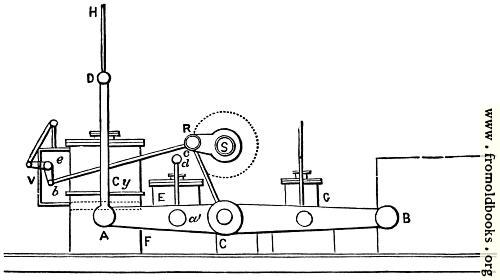
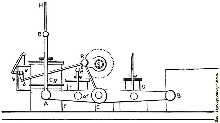
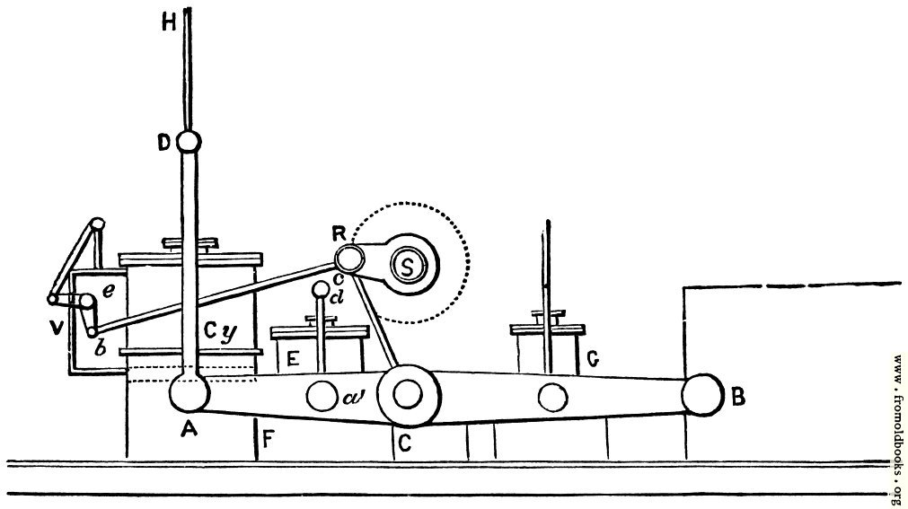
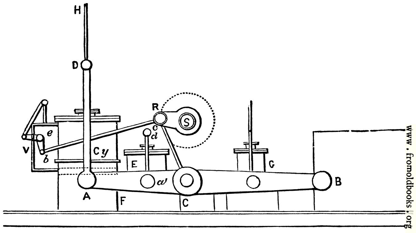
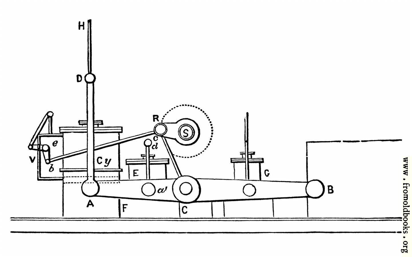
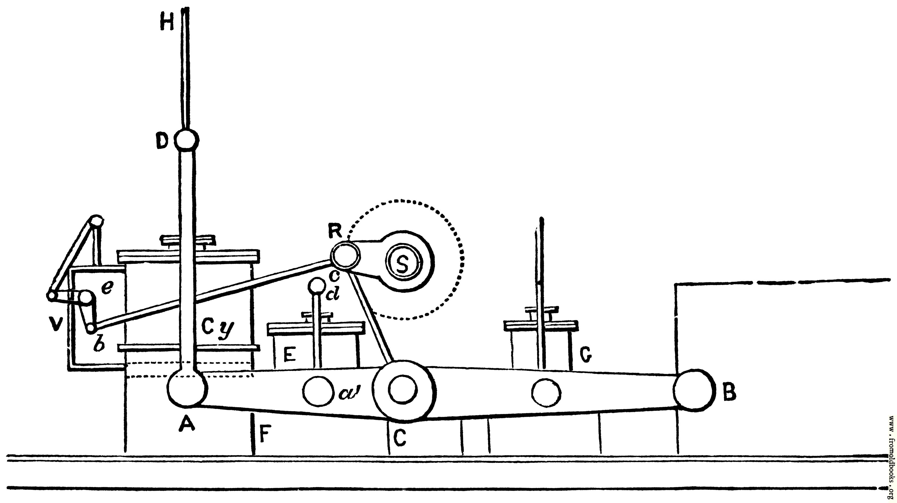
This is a steam engine for driving a ship (a paddle-boat in fact) taken from the Marine Engines chapter:
87. The Side Lever Engines.—The first engine employed to drive the paddle wheel was a side lever, in which the ordinary beam pumping engine was modified to obtain the requisite rotary motion, and the beam placed by the side of the cylinder, condenser, etc., to stow it into as compact a space as possible. In the original side lever the end A of the beam AB was worked up and down on its centre C by the side rods AD, while to the end B was attached the connecting rod working the crank above.
Our figure is a new arrangment of this engine, Cy is the cylinder, in which the piston is shown by dotted lines, the piston-rod is immediately behind AD, and now shown. As the piston moves up or down, the end of the cross head at D lifts and turns it on its centre B; as it reciprocates on its centre B, the connecting rod CR turns the crank RS, which carries with it the paddle shaft S.
E is the air pump, underneath which is the condenser CʹF. The air pump is worked by its side rods a d, in the same was as the larger cylinder Cy is worked; G can be used both as a feed and bilge pump. B is attached to strong framing. The whole works as a lever of the second class.
V the valves are worked by the rod bc working the bell crank lever on its centre e,which gives an alternate upwards and downwards stroke to the slide valves. The details connected with b c are not properly shown, c being attached near to the main shaft.
The piston-rod is compelled to move perpendicularly by means of the guide rod D H moving between two guides.
In all side lever engines there are two side levers and two side rods both to cylinder and pumps; the side rods are connected to the two ends of the piston cross head, which is made, for this purpose, a little longer than the diameter of the cylinder.
The condenser F C beneath the air pump sometimes extends underneath the cylinder.
Get unwatermarked version
Buy print-size file for commercial or other use