![[Picture: Crampton’s Engines]](https://www.fromoldbooks.org/Evers-SteamAndTheSteamEngine/pages/241-Crampton's-Engines/241-Crampton's-Engines-q75-452x500.jpg "[Picture: Crampton’s Engines]")
Download
Buy print-size file for commercial or other use
| 452x500 | 41K | jpg free download |
| 119x132 | 4K | jpg free download |
| 181x200 | 8K | jpg free download |
| 725x802 | 85K | jpg free download |
| 967x1071 | 143K | jpg free download |
| 1720x1904 | 332K | jpg free download |
This site is in danger of going away; please consider the Donate link above...
Buy print-size file for commercial or other use
| 452x500 | 41K | jpg free download |
| 119x132 | 4K | jpg free download |
| 181x200 | 8K | jpg free download |
| 725x802 | 85K | jpg free download |
| 967x1071 | 143K | jpg free download |
| 1720x1904 | 332K | jpg free download |
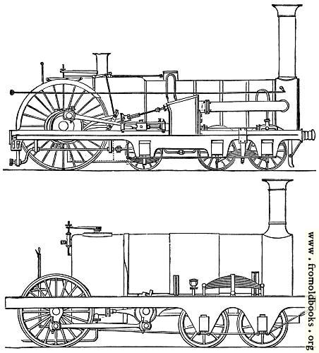
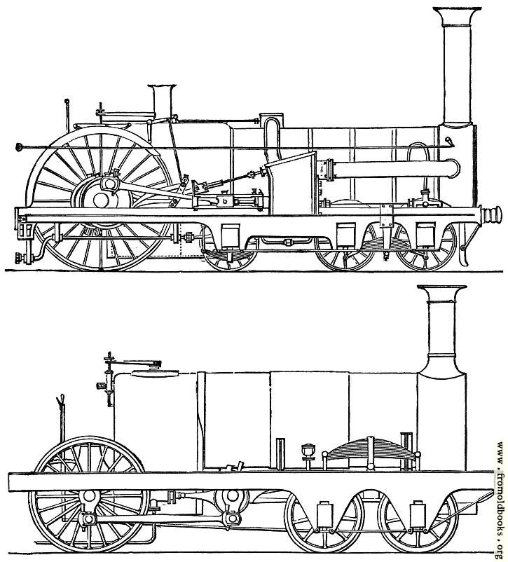
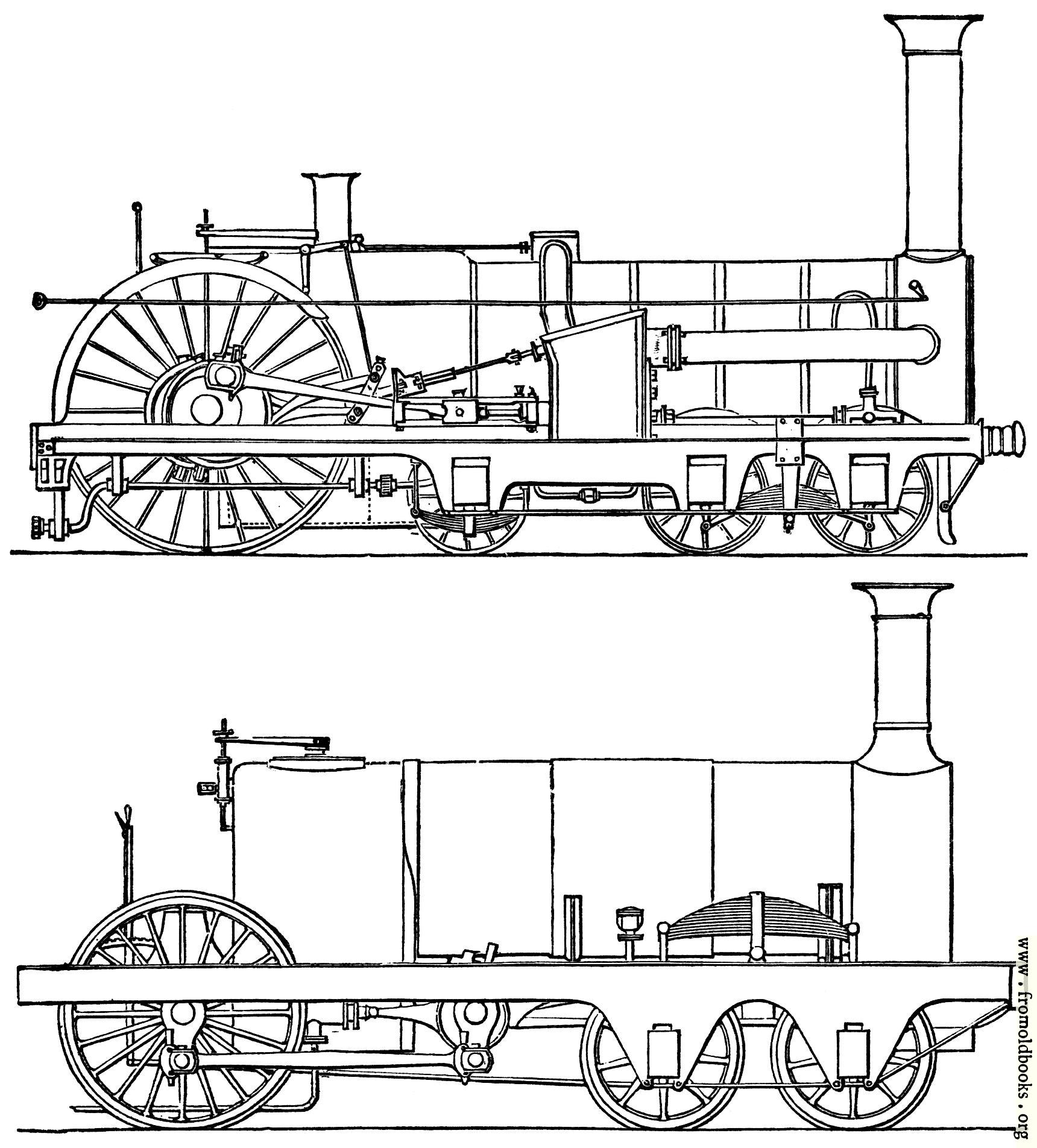
The above figure is another plan of arranging the locomotive. The examples given on page 238 have eight wheels, the general run is six wheels with the large driving wheel in the middle; but in Crampton’s arrangement the large driving wheel is behind. In his engines circular motion is first given, by inside cylinders, to a cranked shaft, supported on bearings fixed upon the frame in the usual manner, and motion is communicated from this shaft to the driving wheels behind the fire box by side rods.
When outside cylinders are used they are placed midway in the length of the boiler, and connected dirctly to the driving wheel. The upper figure is Crampton’s arrangement for outside cylinder, the lower for inside cylinders.” (p. 241)